Rechargeable batteries are widely used in portable electronics, test instruments, communications equipment, industrial sensors, and field-service devices. Their usefulness depends on storing energy in a compact package, but that same stored energy must be controlled. A battery pack can become unsafe if it is charged incorrectly, discharged too deeply, short-circuited, overheated, physically damaged, or used in an atmosphere where a small spark or hot surface can ignite flammable material.
Battery protection is therefore not a single component or checkbox. It is a layered engineering approach that combines cell chemistry, pack design, electronic protection, charger compatibility, thermal control, mechanical construction, certification testing, and correct use. This is especially important for nickel- and lithium-based rechargeable batteries and becomes critical when portable battery-powered equipment is used in hazardous locations such as refineries, mines, grain handling facilities, and chemical plants.
Battery Protection Circuits and Portable Battery Safety Standards
Nickel- and lithium-based rechargeable batteries both require safety controls, but the protection methods differ because the chemistries fail in different ways. Lithium-ion cells are particularly sensitive to overcharge, excessive discharge, short circuit, high temperature, and mechanical abuse. A lithium-ion pack used in portable equipment commonly includes an electronic protection circuit, and larger or more complex packs may include battery management functions that monitor voltage, current, temperature, state of charge, and fault conditions.
Typical lithium-ion protection functions include:
- Overcharge protection, which disconnects or limits charging when a cell reaches its permitted upper voltage limit.
- Over-discharge protection, which prevents cell voltage from falling below the safe operating range.
- Overcurrent and short-circuit protection, which interrupts current during wiring faults, load faults, or accidental bridging of terminals.
- Temperature monitoring, which inhibits charge or discharge outside the permitted thermal range.
- Cell balancing, in multi-cell packs, to reduce voltage mismatch between series-connected cells.
Nickel-cadmium and nickel-metal hydride batteries generally tolerate some abuse differently from lithium-ion, but they are not free of safety requirements. Nickel-based systems still need safe charger design, temperature management, pressure-relief provisions at the cell level, protection against short circuits, and pack construction suitable for the application. Incorrect charging can cause heating, venting, electrolyte leakage, or reduced service life.
IEC 62133 is one of the major international standards used for portable sealed secondary cells and batteries. Current usage is divided by chemistry: IEC 62133-1 applies to nickel systems, while IEC 62133-2 applies to lithium systems. These standards address safety requirements and test methods for portable sealed rechargeable cells and batteries, and they are widely referenced in product compliance programs. They do not replace good engineering judgment; rather, they provide a recognized framework for evaluating foreseeable electrical, mechanical, and thermal stresses.
A practical way to view battery protection is as a set of layers:
| Safety layer | Typical purpose |
|---|---|
| Cell design | Provides internal safety features appropriate to the chemistry and construction |
| Pack electronics | Detects overvoltage, undervoltage, overcurrent, short circuit, and temperature faults |
| Mechanical design | Protects cells from crushing, puncture, vibration, ingress, and terminal damage |
| Charger compatibility | Ensures the pack is charged using the correct algorithm and limits |
| Certification testing | Verifies compliance with applicable safety standards for the intended product category |
| User handling | Reduces misuse such as using damaged packs, bypassing protection, or charging in unsuitable conditions |
No single layer should be treated as complete protection. A certified cell can be made unsafe by poor pack assembly. A good protection circuit can be defeated by mechanical damage. A well-designed pack can be put at risk by an incompatible charger. For portable equipment, protection circuits are best understood as one necessary part of a larger safety system.
Intrinsically Safe Batteries in Hazardous Locations
Intrinsic safety is a protection technique used for electrical equipment in hazardous locations. The basic principle is to limit electrical and thermal energy so the equipment cannot ignite a flammable gas, vapor, dust, or fiber atmosphere under the specified normal and fault conditions. In battery-powered equipment, this means controlling not only normal operating current but also fault energy that could appear during a short circuit, component failure, damaged wiring, or battery fault.
Batteries and portable electronic devices can be ignition sources in several ways:
- A short circuit can produce a spark or arc.
- A damaged cell or pack can release high fault current.
- A component failure can create excessive surface temperature.
- A connector, switch, relay, or loose conductor can generate an ignition-capable transient.
- Mechanical damage can expose conductors or compromise insulation.
Hazardous locations are found anywhere ignitable mixtures may be present. Examples include petrochemical plants, refineries, mines, grain silos, flour mills, offshore platforms, paint spray operations, wastewater treatment facilities, tank farms, loading terminals, and industrial inspection areas around process equipment. In these environments, a portable battery-powered instrument, flashlight, radio, barcode scanner, tablet, gas detector, or sensor may require hazardous-location approval before it can be used.
Intrinsic safety is different from explosion-proof or flameproof protection. An explosion-proof or flameproof enclosure is designed to contain an internal explosion and prevent flame propagation to the surrounding atmosphere. Intrinsic safety instead aims to prevent ignition from occurring in the first place by limiting the energy available in the circuit and by controlling surface temperature.
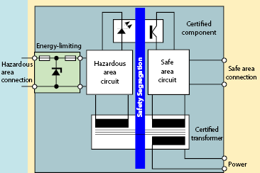
Source: Battery University
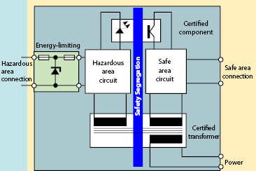
An intrinsically safe system is normally more than a battery and a circuit board. It may include:
- Certified intrinsically safe apparatus used in the hazardous area.
- Associated apparatus, such as a barrier or isolator, located in a safe area or installed according to its approval.
- Approved wiring methods and separation distances.
- Entity parameters or control drawings showing permitted voltage, current, capacitance, and inductance relationships.
- Installation documentation and maintenance procedures.
For battery-operated portable devices, the entire device approval matters. A cell or battery pack may be safe in one certified product but not automatically acceptable in another. Substituting a non-approved battery, charger, connector, or accessory can invalidate the safety concept because the certification is based on the complete system and its defined conditions of use.
Relevant certification frameworks depend on the jurisdiction. In North America, intrinsically safe equipment is commonly evaluated under UL 913 and installed under hazardous-location requirements in the National Electrical Code or Canadian Electrical Code. In IEC-based systems, IEC 60079-11 covers intrinsic safety protection, IECEx provides an international certification scheme, and ATEX applies to equipment placed on the market for explosive atmospheres in the European Union.
Intrinsic safety is most practical for low-power equipment such as instrumentation, sensors, transmitters, gas detectors, communication devices, and portable electronics. It is generally not the preferred method for high-power motors, large lighting loads, or power conversion equipment where the required operating energy is too high to limit below ignition-capable levels. In those cases, other protection methods may be required.
North American Class and Division Hazardous-Location System
The Class and Division system is widely used in North America. In the United States it is defined in the National Electrical Code, NFPA 70 Article 500, with related usage in Canadian Electrical Code practice. The system classifies hazardous locations by the type of material present, the probability of its presence, the material group, and the maximum permitted equipment surface temperature.
The three Classes describe the general type of hazard:
| Class | Hazard type | Typical examples |
|---|---|---|
| Class I | Flammable gases or vapors | Petroleum vapor, propane, hydrogen, solvents |
| Class II | Combustible dusts | Metal dust, coal dust, grain dust, flour dust |
| Class III | Ignitable fibers or flyings | Textile fibers, wood flyings, fiber-processing residues |
Divisions describe how likely the hazardous material is to be present in ignitable concentration.
Division 1 applies where ignitable concentrations are present during normal operation, during repair or maintenance, or because frequent equipment failure can release hazardous material. A process vessel opening, pump seal area, or normally exposed transfer point may create Division 1 conditions depending on the facility classification.
Division 2 applies where ignitable concentrations are normally confined, normally absent, or present only under abnormal conditions. Examples include accidental rupture, ventilation failure, container leakage, or a process upset. Division 2 does not mean no hazard exists; it means the expected presence of an ignitable atmosphere is less frequent or normally abnormal.
Material Groups refine the classification because different substances have different ignition characteristics.
| Classification | Group | Representative material type |
|---|---|---|
| Class I | Group A | Acetylene atmospheres |
| Class I | Group B | Hydrogen or similar high-ignition-risk gases |
| Class I | Group C | Ethylene or similar gases |
| Class I | Group D | Propane, gasoline vapors, and similar gases or vapors |
| Class II | Group E | Conductive metal dusts |
| Class II | Group F | Carbonaceous dusts such as coal or coke dust |
| Class II | Group G | Grain, flour, starch, or similar combustible dusts |
Temperature codes are another essential part of the marking. Electrical equipment in a hazardous location must not reach a surface temperature capable of igniting the surrounding material. The temperature code therefore limits the maximum surface temperature of the equipment under the conditions covered by its approval. The required code depends on the ignition temperature of the gas, vapor, dust, fiber, or flying material in the classified area.
A complete North American classification assembles these elements. For example, an area where propane may be present in ignitable concentration during normal operation could be classified as Class I, Division 1, Group D. Equipment used there must be approved for that classification and must also meet the applicable temperature-code requirement and installation rules.
For battery-powered equipment, the marking should be checked against the actual area classification. A portable instrument approved only for Class I, Division 2 is not automatically acceptable in Class I, Division 1. A device approved for one gas group may not be suitable for a more severe group. Battery replacement instructions are also part of the safety basis; using an unapproved battery can change fault current, thermal behavior, enclosure integrity, or charging safety.
Zone Classification in Europe and IEC-Based Systems
The Zone system is used in Europe and in many IEC-based jurisdictions. In the European Union, ATEX requirements apply to equipment intended for use in potentially explosive atmospheres. IECEx certification is used internationally as a route for demonstrating compliance with IEC hazardous-location standards. Some countries recognize both Class/Division and Zone concepts, but equipment selection must follow the rules accepted by the local authority and site classification documents.
For gases and vapors, the Zone system classifies the likelihood and duration of an explosive atmosphere as follows:
| Gas or vapor zone | Presence of explosive atmosphere |
|---|---|
| Zone 0 | Present continuously or for long periods |
| Zone 1 | Likely to occur during normal operation |
| Zone 2 | Not likely during normal operation, or present only for a short time under abnormal conditions |
For combustible dust atmospheres, the corresponding dust zones are:
| Dust zone | Presence of combustible dust atmosphere |
|---|---|
| Zone 20 | Present continuously or for long periods |
| Zone 21 | Likely to occur during normal operation |
| Zone 22 | Not likely during normal operation, or present only for a short time under abnormal conditions |
Equipment Groups identify the broad environment. Group I is used for mining applications. Group II applies to surface industries with gas or vapor hazards. Group III applies to dust environments. Within these groups, subgroups further distinguish ignition behavior.
For gas and vapor atmospheres, Group II is divided into IIA, IIB, and IIC. IIC is the most severe gas subgroup and includes highly ignitable gases such as hydrogen or acetylene depending on the classification context. Equipment certified for a more severe subgroup may often cover less severe subgroups when allowed by the approval, but the actual certificate and marking must be checked.
For dust atmospheres, Group III subgroups are commonly used:
- IIIA for combustible flyings.
- IIIB for non-conductive dust.
- IIIC for conductive dust.
Temperature classes, commonly T1 through T6, define maximum equipment surface-temperature limits. The selected temperature class must be matched against the ignition temperature of the hazardous atmosphere. This is especially important for battery-powered electronics because heat may come from cells, regulators, processors, displays, radios, charging contacts, or fault-protection devices.
The Zone system and the North American Class/Division system are not identical, but broad comparisons are often useful. A propane environment present during normal operation may correspond broadly to Class I, Division 1, Group D in North American terminology and Zone 1, Group IIA in IEC or European terminology. This kind of comparison is helpful for orientation, but it should not be used as a substitute for a formal hazardous-area classification or equipment certificate review.
For engineers selecting battery-powered equipment, the practical questions are straightforward:
- What hazardous material may be present: gas, vapor, dust, fiber, or flying?
- How often and for how long can an ignitable atmosphere exist?
- What group or subgroup applies to the material?
- What temperature class is required?
- Is the complete device, including its battery and accessories, certified for that exact use?
- Are installation, charging, replacement, and maintenance instructions compatible with the approval?
Battery protection circuits reduce electrical and thermal risk inside the pack, while intrinsic safety controls ignition risk at the equipment and system level. In ordinary portable products, protection circuits are mainly about preventing battery abuse and product failure. In hazardous locations, the same battery energy must also be evaluated as a possible ignition source. Safe design therefore requires both battery engineering discipline and correct hazardous-location classification.
References
- Intrinsic Safety 101 - Hazardous Locations | MicroWatt Controls. (n.d.). https://microwatt.com/news-resources/intrinsic-safety-101-hazardous-locations
- An Introduction to Intrinsic Safety | Instrumart. (n.d.). https://www.instrumart.com/blog/applications/611/an-introduction-to-intrinsic-safety
- Intrinsic Safety – Understanding the Lingo. (n.d.). https://telaeris.com/what-is-intrinsic-safety
- Intrinsic safety - Wikipedia. (n.d.). https://en.wikipedia.org/wiki/Intrinsic_safety
- Intrinsic Safety Guide | ATEX/IECEx/Class I Div | ISS | Intrinsically Safe Store. (n.d.). https://intrinsicallysafestore.com/blog/understanding-intrinsic-safety-guide
- Intrinsic Safety Type of Protection: An Overview. (n.d.). https://blog.pepperl-fuchs.com/en/2024/intrinsic-safety-type-of-protection-a-fundamental-overview
- What Does Intrinsically Safe Mean?. (n.d.). https://www.flyability.com/blog/what-does-intrinsically-safe-mean
- UL 913: Intrinsically Safe Equipment | US Made Supply. (n.d.). https://usmadesupply.com/resources/building-codes-standards/safety-compliance/ul-913
- understanding - intrinsic safety. (n.d.). https://tsi.com/getmedia/397dfb71-3264-4d32-8a97-a591479f7fe6/EXPMN-017_Understanding_Intrinsic_Safety-US-web?ext=.pdf
- Hazardous Locations: How to Provide Explosion Protection and Create Intrinsically Safe Systems - NI. (n.d.). https://www.ni.com/en/support/documentation/supplemental/15/hazardous-locations--how-to-provide-explosion-protection-and-cre.html