USB was created as a standardized way to connect computers and peripherals, but it quickly became one of the most common low-voltage charging interfaces for portable electronics. Phones, cameras, Bluetooth accessories, power banks, tablets, and many small instruments now depend on some form of USB power.
That convenience can hide important engineering limits. A USB connector does not, by itself, define how much charging power is available. Current may be limited by the USB generation, the port type, the charger design, the cable, the device being charged, and whether any power negotiation has occurred. A device that charges quickly from one USB port may charge slowly, refuse to charge, or overload another.
For battery-powered products, the practical question is not simply whether the plug fits. It is whether the source, cable, and load agree on a safe voltage and current.
USB Charging Basics and Early Port Limits
The Universal Serial Bus, or USB, was introduced in the mid-1990s as a common interface for data connection and limited peripheral power. The original development involved several major computer and electronics companies, including Compaq, DEC, IBM, Intel, Microsoft, NEC, and Nortel. Its first role was not high-power battery charging; it was to simplify connections for keyboards, mice, printers, storage devices, and other computer peripherals.
Early USB power was therefore modest. A standard downstream USB 1.x or USB 2.0 host port commonly supplied 5 V with a maximum current of up to 500 mA after proper enumeration by the host. That is about:
- 5 V × 0.5 A = 2.5 W
For a small peripheral or a low-capacity battery, 2.5 W may be adequate. For a phone, tablet, large power bank, or other device with a larger lithium-ion pack, it is slow. For a discharged device that tries to draw more than allowed, it can also be unreliable.
A standard host port is data-capable and normally expects the connected device to follow USB power rules. Before a peripheral is configured, it may be allowed only a lower initial current. After enumeration, the host can permit more current within the specification. This matters because a computer USB port is not just a 5 V supply; it is part of a controlled bus system intended to protect the host and other connected devices.
If a port is weak, noncompliant, current-limited, or already loaded by other devices, several outcomes are possible:
- the battery charges very slowly;
- the device switches between charging and not charging;
- the host disables power to the port;
- the computer displays an over-current warning;
- the connected device falls back to a lower-power mode.
This is why early USB charging was often inconsistent. The connector looked universal, but the available power was not always enough for the battery being charged.
Power Limits, Dedicated Charging Ports, and USB Power Delivery
USB 2.0 power is limited for larger batteries because it provides only about 2.5 W from a standard downstream port. Charging a device with a multi-watt-hour battery at that power level can take many hours, especially if the device is awake and consuming energy while it charges.
USB 3.0 improved the standard downstream current limit to 900 mA at 5 V, or about 4.5 W. That was a useful increase for bus-powered devices and smaller charging loads, but it still did not turn a normal computer port into a high-power charger.
A simplified comparison is useful:
| USB power source type | Typical voltage | Supported current discussed here | Approximate power | Main use |
|---|---|---|---|---|
| USB 1.x / USB 2.0 standard downstream port | 5 V | up to 500 mA after proper enumeration | 2.5 W | Data port with limited peripheral power |
| USB 3.0 standard downstream port | 5 V | up to 900 mA | 4.5 W | Data port with increased bus power |
| USB Battery Charging dedicated charging port | 5 V | commonly up to 1.5 A | 7.5 W | Charger-oriented port, generally not for data |
| USB-C Type-C current mode | 5 V | 1.5 A or 3.0 A when indicated | 7.5 W or 15 W | Basic USB-C charging without full PD voltage negotiation |
| USB Power Delivery | negotiated | depends on source, sink, and cable | up to 100 W in older common implementations; up to 240 W with USB PD 3.1 EPR | Higher-power charging and power supply |
The USB Battery Charging Specification, first released in 2007 and later developed through versions such as BC 1.2, addressed the gap between data ports and wall chargers. It defined charging port types, including the Dedicated Charging Port. A DCP is intended primarily to provide charging power rather than a normal USB data connection. Under BC 1.2 practice, a DCP commonly supports up to 1.5 A at 5 V, or about 7.5 W.
The distinction is important:
- A data-capable host port must manage communication and power according to USB rules.
- A dedicated charging port can signal that more current is available for charging, but it may not support data transfer.
Before charging behavior became more standardized, many products used proprietary resistor or voltage signatures on the data pins to indicate charger capability. This helped some devices charge faster from specific chargers, but it also created compatibility problems. A device might charge quickly from one adapter and slowly from another, even if both had the same connector.
Y-cables and accessory charging adapters were also used as workarounds. A Y-cable could connect one branch to a data port and another branch to a charging source, allowing data communication while drawing extra power elsewhere. Although this may appear practical, USB compliance rules prohibit the use of a Y-cable for a peripheral that exceeds the power allowed by the USB specification it is designed for. The compliant approach for a device needing more power than the bus can provide is to make it self-powered, using its own external supply or charger.
Modern USB Power Delivery, usually called USB PD, is a more capable and formal solution. USB PD is not simply a USB-C-shaped connector or a promise that a charger is powerful. It is a negotiated power protocol. The source advertises available power profiles, the sink requests a supported option, and power is supplied only when the negotiation succeeds.
This negotiation is central to safety and compatibility. A high-power charger may be able to supply far more than a small device needs, but the device should request only a compatible voltage and current. Conversely, a laptop may need much more power than a small phone charger can deliver. In that case it may charge slowly, operate without charging, or reject the charger.
Modern USB PD 3.1 includes Extended Power Range operation that can reach up to 240 W when the charger, device, cable, and specification support it. That maximum should not be generalized to all USB-C ports. Many USB-C ports support only basic 5 V charging, lower PD power levels, data-only operation with limited current, or manufacturer-specific restrictions.
Sleep-and-Charge USB Ports
Most computers remove USB power when the computer is fully shut down. Some also disable USB power during sleep or hibernate states. This behavior conserves energy and prevents peripheral drain, but it is inconvenient when the computer is being used as a charging source.
To address this, many laptops and desktops include one or more sleep-and-charge USB ports. These ports can remain powered when the computer is asleep, hibernating, or turned off, depending on the system design and settings. A user can plug in a phone or other small device and continue charging without booting the computer.
Manufacturers use different names and markings for this feature. Dell has used the name PowerShare and may identify the port with a lightning-bolt icon. Toshiba has used the term USB Sleep-and-Charge. Some systems mark the port with a battery symbol, a USB symbol near a battery drawing, or a special icon near the connector.
Color is not a reliable standard. Sleep-and-charge ports may be red, yellow, or another color, but there is no universal marking scheme. A yellow USB port on one computer may indicate standby charging, while a yellow or red port on another product may mean something different or nothing at all. The only dependable sources are the equipment manual, BIOS or UEFI settings, or the manufacturer utility supplied with the system.
Sleep-and-charge behavior can also depend on configuration. Some laptops allow the feature only when the AC adapter is connected. Others permit it from the internal battery until the battery reaches a defined low-charge threshold. Some systems require the feature to be enabled in BIOS, UEFI, or a vendor power-management application before the port remains active.
From a battery perspective, standby charging is useful but not free. If the laptop is not connected to AC power, energy delivered to the external device comes from the laptop battery. Charging a phone from a sleeping notebook can noticeably reduce the notebook’s available runtime, especially if the external device has a large battery or is left connected for many hours.
A practical troubleshooting sequence is:
- Confirm which port supports sleep-and-charge; not all ports on the same computer do.
- Check BIOS, UEFI, operating-system, or vendor utility settings.
- Test with the AC adapter connected and disconnected.
- Use a known-good cable and device.
- Remember that the port may supply limited current even when the feature is enabled.
USB-C Connectors, Reversible Cables, and High-Power Charging
USB Type-C changed the physical interface as much as the charging experience. The Type-C connector has 24 pins and is reversible, so it can be inserted in either orientation. It can support power, data, and alternate-mode functions such as video, but those functions depend on the implementation. The connector shape alone does not guarantee a data rate, a charging wattage, Thunderbolt support, USB4 support, or display output.
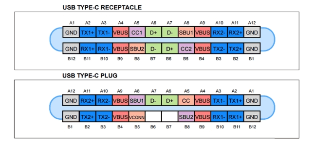
Source: Battery University
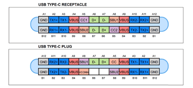
For basic USB-C power without full USB Power Delivery voltage negotiation, Type-C defines current advertisement over the configuration channel. In addition to baseline USB current, a USB-C source can indicate support for 1.5 A or 3.0 A at 5 V. Those levels correspond to:
- 5 V × 1.5 A = 7.5 W
- 5 V × 3.0 A = 15 W
This is a significant improvement over the 2.5 W commonly associated with USB 2.0 standard downstream charging. It is still not the same as laptop-class USB Power Delivery. Higher power levels such as 60 W, 100 W, or the newer 240 W maximum under USB PD 3.1 Extended Power Range require USB PD negotiation and compatible hardware.
The difference between USB-C and USB PD is a common source of confusion:
| Term | What it describes | What it does not guarantee |
|---|---|---|
| USB-C | Physical 24-pin reversible connector and cable system | High wattage, high data speed, video, Thunderbolt, or USB4 support |
| USB 3.1 / USB 3.2 | USB data-generation naming | Connector type or charging power by itself |
| USB Power Delivery | Negotiated power protocol | Availability on every USB-C port |
| E-marked cable | Cable with electronics that report capability | That the charger or device supports the desired power level |
Older USB-C PD implementations commonly reached up to 100 W, typically by using higher voltages and currents than legacy 5 V USB. USB PD 3.1 Extended Power Range raises the maximum to 240 W when all required conditions are met. In practical charging systems, the actual power is limited by the lowest-capability element in the chain: the charger, the device, the cable, or the port controller.
Cable rating matters especially above 3 A. Currents above 3 A require properly rated electronically marked cables so the system can identify the cable’s capability before allowing high-power operation. Using an underrated or damaged cable in a high-current application can cause voltage drop, heating, unreliable charging, or protective shutdown. Well-designed USB PD systems should avoid unsafe power levels by negotiation, but cable quality and correct rating remain important engineering controls.
USB-C also introduced transition issues. A USB-C receptacle on a small battery-powered device may be wired only for basic charging. A laptop USB-C port may support charging input, display output, and high-speed data, or it may support only a subset. A USB-C to USB-A cable can enable compatibility with older chargers, but it cannot make a legacy USB-A port provide USB PD behavior beyond what that port and cable design support.
For battery charging, the safest interpretation is conservative: the connector tells you what can be plugged in, not what power will be delivered. The delivered power is determined only after the source, sink, and cable establish what they can safely support. When designing or selecting a charger for a battery-powered product, verify the supported USB charging mode, maximum input power, cable requirements, and fallback behavior rather than relying on connector appearance.
References
- Battery University | BU-411: Charging from a USB Port. (n.d.). http://www.batteryuniversity.com/article/bu-411-charging-from-a-usb-port
- Battery University | BU-411: Charging from a USB Port. (n.d.). https://www.batteryuniversity.com/article/bu-411-charging-from-a-usb-port
- USB hardware - Wikipedia. (n.d.). https://en.wikipedia.org/wiki/USB_hardware
- What is the maximum power supplied by a USB 3.0 port? - Super User. (n.d.). https://superuser.com/questions/1460313/what-is-the-maximum-power-supplied-by-a-usb-3-0-port
- The History and Evolution of USB Charging Standards | ElcomSoft blog. (n.d.). https://blog.elcomsoft.com/2026/01/the-history-and-evolution-of-usb-charging-standards
- What is USB-C Power Delivery? | Cable Matters Blog. (n.d.). https://www.cablematters.com/Blog/USB-C/what-is-usb-c-power-delivery
- The History of USB Standards from 1.0 to USB4 | Same Sky®. (n.d.). https://www.sameskydevices.com/blog/the-history-of-usb-standards-from-1-to-usb4
- USB Types Guide 2026: What Are They and What They Do? - Anker US. (n.d.). https://www.anker.com/blogs/cables/how-to-identify-different-types-of-usb-cables-a-brief-guide
- USB C and USB 3.1 (now called USB 3.2) Explained | OnLogic. (n.d.). https://www.onlogic.com/blog/usb-type-c-and-usb-3-1-explained
- USB Type-C vs. USB-PD: The Key Differences. (n.d.). https://community.infineon.com/t5/Knowledge-Base-Articles/USB-Type-C-vs-USB-PD-The-Key-Differences/ta-p/249584