Charger chips, also called battery charger ICs, are integrated circuits that control how rechargeable cells and packs receive charge. They became widely useful when charger ICs appeared in the 1980s for nickel-cadmium and nickel-metal-hydride chargers, where reliable charge termination could be difficult with purely discrete circuitry. By putting much of the sensing, regulation, timing, and control logic into one device, charger chips reduced the amount of custom analog design required.
Modern charger ICs are used across small portable products, industrial equipment, smart battery systems, power tools, and embedded backup supplies. Their job is not simply to connect a power source to a battery. A charger must respect the target chemistry, cell count, voltage limit, current limit, temperature behavior, system load, and safety requirements. Lithium-ion chargers commonly manage controlled constant-current and constant-voltage charging, while nickel-based batteries need different termination methods.
Charger chips can be simple fixed-function devices or programmable power-management controllers with switching converters, FET control, communication interfaces, fault handling, and coordination with a battery management system. They simplify charger design, but they do not eliminate engineering work: the battery, PCB layout, thermal path, input supply, and external power components still determine whether the finished charger is safe and reliable.
Source: Battery University
What Charger Chips Do in a Battery Charger
A charger chip is the control element of a battery charging circuit. It monitors electrical conditions, controls power flow, and follows the charging profile required by the battery chemistry. In a basic design, the IC may regulate charge current and voltage directly. In a higher-power design, it may drive external MOSFETs or coordinate a switching power stage that performs the actual energy conversion.
The original benefit of charger chips was design simplification. NiCd and NiMH cells can be robust in use, but their charging behavior is less straightforward than merely applying a fixed voltage. They require detection of charge completion by methods appropriate to nickel chemistry, and poor termination can lead to heating, overcharge stress, or incomplete charge. Integrated charger controllers made it easier to build repeatable chargers without designing all detection and timing circuits from scratch.
For lithium-ion batteries, the typical charger profile is more voltage-defined. A common Li-ion charger controls current during the constant-current phase, then holds the cell or pack at the required regulation voltage during the constant-voltage phase until termination conditions are met. This apparent simplicity does not remove the need for protection. Li-ion cells must be charged within their specified voltage, current, and temperature limits, and the charger must be selected for the exact cell count and chemistry variant.
A charger IC usually provides or controls several core functions:
- Charge-current regulation to limit current delivered to the battery.
- Voltage regulation to prevent charging above the intended terminal voltage.
- Charge-state sequencing such as pre-charge, fast charge, top-off, termination, and recharge behavior.
- Power switching through internal or external FETs, depending on the IC and power level.
- Fault response when battery voltage, time, current, temperature, or input conditions are outside the expected range.
The IC is only part of the charger. Practical circuits still need external resistors, capacitors, sense elements, connectors, protection parts, and PCB copper area for heat spreading. Switching charger designs also need magnetic components such as inductors, suitable power switches or integrated switch stages, diodes or synchronous rectification elements where applicable, and careful layout to manage noise and thermal stress.
Built-In Regulation, Switching, and Safety Functions
The most visible function of a charger chip is regulation. The IC compares battery and input conditions against internal references or programmed settings, then adjusts its control output to keep current and voltage within the intended limits. This regulation may be implemented in a linear pass path, a switching converter, or a more complex power-path arrangement that can power the system and charge the battery at the same time.
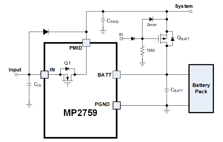
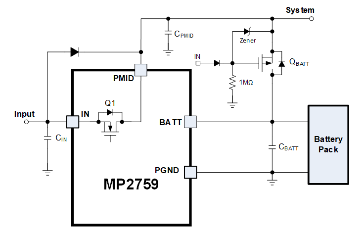
Modern charger chips may include internal FET switches or provide gate-drive signals for external FETs. These switches control whether current flows from the input to the system, from the input to the battery, or from the battery to the system. In power-path chargers, this control can allow a device to operate from an adapter while the battery charges, and it can prevent undesirable reverse current when the adapter is removed.
Safety functions vary by IC, but many Li-ion charger chips integrate or coordinate protection features needed for safe charging. Depending on the device, these may include:
- overvoltage detection;
- overcurrent limiting;
- short-circuit response;
- thermal regulation or thermal shutdown;
- battery temperature qualification when used with a thermistor input;
- input undervoltage or overvoltage handling;
- fault signaling to a host controller.
A time-out timer is another common safeguard. If the expected battery response does not occur within the permitted charging interval, the timer can halt charging and report a fault. This is useful because a flawed, disconnected, deeply damaged, or mismatched battery may not follow the normal voltage and current progression. A timer does not prove a battery is healthy, but it prevents indefinite charging when the process is abnormal.
Some charger ICs also provide charge-status outputs. In a simple appliance, these outputs may drive LEDs for charging, full, and fault states. In an embedded product, they may be read by a microcontroller or power-management IC. More advanced battery systems may communicate with a fuel gauge, battery management system, or host processor to coordinate charging with state-of-charge estimates, pack limits, and system operating modes.
Multi-cell systems add more complexity. Some charger ICs support cell balancing directly, while others work alongside a separate BMS that handles monitoring and balancing. In many larger packs, the charger does not individually protect every cell; instead, it follows limits communicated or enforced by the pack electronics.
A useful design distinction is the difference between linear and switching charger ICs. A linear charger is usually simpler, compact, and quiet from an EMI standpoint, but it dissipates the voltage difference between input and battery as heat. That can be acceptable at low currents or when the input voltage is close to battery voltage, but thermal limits quickly become important. A switching charger uses buck, boost, or buck-boost conversion to transfer energy more efficiently over a wider range of input and battery voltages. Switching designs are more complex and layout-sensitive, but they can support higher charge currents and broader power-source compatibility.
Advanced Operating Modes and Practical Limits
Charger chips often include operating modes that handle real-world battery conditions. One important example is pre-charge conditioning, sometimes described as a boost or wake-up stage. If a battery is deeply discharged or inactive, the charger may apply a reduced controlled current before allowing normal fast charge. This limits stress on the battery and gives the circuit a chance to confirm that the battery voltage is recovering as expected.
Another useful function is sleep mode or low-quiescent-current operation. Products may sit in storage or on a shelf for long periods. During that time, housekeeping current from the charger circuit can slowly drain the battery if not managed. A low-power mode reduces this standby burden and helps preserve stored energy.
Many charger chips also support automatic recharge. If a battery remains connected to a charger and a parasitic load or standby drain lowers its voltage below a preset threshold, the IC may restart charging. This behavior is common in products that are left in docks, cradles, or always-connected power systems. The goal is to maintain readiness without continuously forcing a full-rate charge.
These functions make charger ICs convenient, but they do not make them universal. Many charger chips use a fixed or narrowly configurable charge algorithm. That is suitable for standard cells and predictable applications, but it can be restrictive when a design needs specialty termination rules, unusual cell arrangements, or adaptive behavior based on pack history.
A charger chip selected for one chemistry, voltage range, and cell count should not be assumed to support another battery type. A Li-ion charger IC is not automatically suitable for NiMH, NiCd, lead-acid, lithium iron phosphate, or another lithium chemistry unless the datasheet explicitly supports the required profile and limits. Even within lithium-based batteries, regulation voltage, allowed current, temperature limits, and protection expectations can differ.
Another practical limitation is aging. Many charger chips do not automatically optimize charge current for older batteries with reduced charge acceptance. An aged cell may heat more, reach voltage limits sooner, or behave differently from a new cell. A fixed-function charger may still follow its programmed limits, but it may not infer the best current or termination strategy for battery health.
Programmable charger ICs reduce some of these limitations. Devices with I2C, SMBus, or similar control interfaces can expose configurable charge current, regulation voltage, input-current limits, status registers, and fault information. However, programmability is not unlimited freedom. The safe operating envelope is constrained by the IC ratings, firmware, battery pack design, BMS limits, thermal design, and applicable safety requirements. A programmable setting that is electrically possible is not necessarily safe for the selected battery.
Dedicated Charger ICs Versus Microcontroller-Based Designs
A designer does not always have to use a fixed-function charger chip as the only control element. An alternative is a microcontroller-based design using firmware, an analog front end, sensors, ADC measurements, and external power components to implement a custom charging algorithm. In some products, the microcontroller supervises a charger IC. In others, it directly controls the power stage through analog or digital control circuitry.
The main advantage of a microcontroller-based approach is flexibility. Firmware can support product-specific behavior that a fixed charger IC may not provide, such as:
- chemistry identification or battery-code interpretation when the hardware supports it;
- custom charge termination rules;
- derating based on temperature, age, or operating mode;
- pack authentication or host communication;
- event logging and diagnostic reporting;
- coordination with system loads and power budgeting;
- field updates when charging policy needs refinement.
This flexibility is valuable in smart battery systems, industrial equipment, medical devices, larger packs, or products with multiple battery options. It can also help when the charger must interact closely with the system load. For example, a charger that senses combined battery and system current may not terminate correctly if the system load masks the true battery current. A host controller or BMS can sometimes make better decisions by measuring battery current separately.
The tradeoff is engineering complexity. A microcontroller-based charger requires reliable firmware, accurate measurements, robust fault handling, and safe default states if software fails or communication is lost. It may also require more validation than a standard charger IC used in a conventional reference design. For safety-critical charging, firmware must not become the only layer preventing hazardous conditions.
Cost comparisons are not always obvious. The manufacturing cost of a microcontroller can be comparable with a charger chip in some designs, especially if the product already includes a host controller. But the IC price is only one part of total charger cost. External components, power-stage parts, connectors, thermal design, input protection, isolation where required, certification effort, test time, and manufacturing complexity often dominate the final cost.
| Design approach | Main strengths | Main limitations |
|---|---|---|
| Dedicated charger IC | Compact, repeatable, low firmware burden, suitable for standard profiles | Less flexible, usually tied to a chemistry and cell count range |
| Programmable charger IC | Configurable limits, status reporting, host coordination | Still constrained by IC ratings and battery safety requirements |
| Microcontroller-based control | Custom algorithms, logging, system-specific behavior | More firmware, validation, sensing, and fail-safe design effort |
Dedicated charger ICs remain attractive when the charging requirement is standard, compact, cost-sensitive, and does not require extensive customization. They are especially effective when the selected battery, input source, current level, and charge profile match the IC manufacturer’s intended application.
Factory-Configured Charger Modules
Factory-configured charger modules provide another path between a raw IC design and a fully custom charger. A module is a predesigned charging assembly configured for a specific battery voltage, charge current, and charge algorithm. Instead of building every regulation, sensing, thermal, and interface circuit from individual components, the designer integrates a ready-made charger block into the product or system.
This approach resembles the way ready-made AC power supplies became common as an alternative to designing a custom supply for every product. The engineering team still has to verify fit and safety, but much of the circuit implementation has already been packaged and tested by the module supplier.
One useful feature available in some modules is seamless DC-DC conversion. A module may be able to charge a battery at a higher voltage than the available input provides by using boost or buck-boost conversion. This is important when the input source is a low-voltage adapter, vehicle rail, USB-derived supply, or solar source and the battery pack requires a higher charging voltage.
Factory-configured modules may also provide options such as SMBus communication, solar charging support, discharge for calibration, and display functions. These features can be useful in smart-battery systems, maintenance chargers, field equipment, and products where state reporting or calibration cycles are part of normal operation.
Selection still requires careful review. Before using a charger module, verify at least the following:
- battery chemistry and cell count;
- maximum charge voltage and allowed tolerance;
- charge-current setting and battery manufacturer limit;
- input-voltage range and input-current limit;
- thermal rating at the intended ambient conditions;
- required communication interface, such as SMBus;
- compatibility with the battery pack protection circuit or BMS;
- behavior with deeply discharged batteries;
- fault reporting and reset behavior;
- mechanical mounting, cooling, and connector ratings;
- safety approvals or compliance requirements for the end product.
A module can reduce design effort, but it should not be treated as universally compatible. The battery pack, charger module, input supply, and end equipment must operate as a system. Correct matching is especially important for lithium-based batteries, multi-cell packs, and systems where the product load remains active during charging.
In practice, charger chips and charger modules serve the same engineering goal: controlled energy transfer into a rechargeable battery without exceeding the battery’s limits. The right choice depends on how standard the charging requirement is, how much programmability is needed, how much validation effort the project can support, and how tightly the charger must interact with the rest of the product.
References
- Battery University | BU-414: How do Charger Chips Work?. (n.d.). http://www.batteryuniversity.com/article/bu-414-how-do-charger-chips-work
- How Do Charger Chips Work in Modern Devices. (n.d.). https://www.large-battery.com/blog/how-do-charger-chips-work-in-modern-electronic-devices
- Why Do Chargers Need Chips?. (n.d.). https://www.bwoohk.com/blog/why-do-chargers-need-chips
- Beginner’s Guide to Battery Charger PCB Components: What You Need to Know. (n.d.). https://www.allpcb.com/allelectrohub/beginners-guide-to-battery-charger-pcb-components-what-you-need-to-know
- Battery Charger IC Fundamentals. (n.d.). https://www.monolithicpower.com/learning/resources/battery-charger-fundamentals
- Need a little guidance with battery charge ICs and similar. (n.d.). https://www.eevblog.com/forum/projects/need-a-little-guidance-with-battery-charge-ics-and-similar
- How Battery Chemistry Affects Battery Charger IC Selection. (n.d.). http://www.monolithicpower.com/learning/resources/battery-management-systems-how-battery-chemistry-affects-battery-charger-ic-selection
- Chips charge up for lithium-ion. (n.d.). https://www.eetimes.com/chips-charge-up-for-lithium-ion
- AdvanceTec 4-Slot Conditioning Charger For Vertex Standard VX-414 Lithium Batteries. (n.d.). https://store.tac1systems.com/advancetec-4-slot-conditioning-charger-for-vertex-standard-vx-414-lithium-batteries
- BQ40Z50-R2: Selecting right Charger IC for 4S-10S Li-ion Battery Pack - Power management forum - Power management - TI E2E support forums. (n.d.). https://e2e.ti.com/support/power-management-group/power-management/f/power-management-forum/1456699/bq40z50-r2-selecting-right-charger-ic-for-4s-10s-li-ion-battery-pack