Internal-resistance measurements are useful because a rising reading can indicate degradation, reduced high-current performance, or approaching end of service life. The relationship is particularly useful for some nickel-based batteries, but resistance is not a universal battery-health measurement. A reading is meaningful only when the measurement method and operating conditions are understood.
The most reliable practice is to record a baseline for each cell, module, or battery when it is installed and trend changes over time. Comparing unrelated batteries can be misleading: manufacturing variation alone can produce different resistance readings among otherwise similar lead-acid batteries. Internal resistance also varies with temperature, state of charge, connection quality, recent charge or discharge history, and the frequency or duration of the test.
Resistance should therefore be considered alongside capacity, temperature, state of charge, and performance in the actual application. A battery can retain a relatively stable resistance while its capacity declines, particularly in some modern lead-acid and lithium-ion designs. Conversely, a higher apparent resistance may result from a low state of charge or cold temperature rather than permanent aging.
Why Internal Resistance Is Useful—and Limited
Internal resistance represents losses inside a battery. When current flows, these losses produce a voltage drop and dissipate energy as heat. A battery with higher resistance generally delivers less voltage under load and may be unable to supply the current required by a starter, inverter, motor, or other demanding load.
A rising trend can be a useful warning of aging, but the strength of that warning depends on chemistry and construction. Nickel-based batteries often show a more useful relationship between increasing resistance and end-of-life than some modern lead-acid and lithium-ion batteries. In the latter chemistries, resistance may remain fairly flat through much of the service life while usable capacity gradually falls.
This is why a single resistance value should not be treated as a direct state-of-health or capacity reading. A partially charged healthy battery and a fully charged weak battery can produce similar apparent resistance values. Temperature can have a similarly large effect, especially when electrochemical reaction rates and electrolyte conductivity change with temperature.
For field monitoring, record at least:
- The battery, cell, or module identity.
- Test method and, for AC methods, the test frequency.
- Temperature and approximate state of charge.
- Rest time since charging or discharging.
- Probe arrangement, terminal condition, and connection details.
- Voltage, current, and the resulting resistance or conductance value.
Trending the same unit under repeatable conditions is usually more informative than comparing a reading with a generic value from another battery. Manufacturing tolerances can be significant; the supplied reference reports variation of approximately 5–10% among some lead-acid battery batches, particularly stationary units. Such variation makes an installation baseline especially important.
Resistance, Impedance, and the Battery Equivalent Circuit
Resistance is the opposition to current associated with energy dissipation. It is measured in ohms (Ω). In a purely resistive circuit, voltage and current change together and are in phase. The voltage drop can be described with Ohm’s law:
R = ΔV / ΔI
Impedance is the broader opposition presented to an alternating signal. It includes the resistive component and frequency-dependent effects from capacitance and inductance. Impedance is also expressed in ohms, but it can have both a real component and a reactive component. The phase relationship between voltage and current contains additional information that a simple DC resistance value does not.
Conductance is the reciprocal of resistance and is measured in siemens (S). In AC work, admittance is the reciprocal of impedance. Commercial battery testers may use the term conductance for a measurement-derived value or a proprietary battery-health estimate, so the instrument manual and test method matter.
Capacitive reactance decreases as frequency increases, while inductive reactance increases with frequency. These relationships explain why a battery can have different measured values when tested with a short DC pulse, a low-frequency AC signal, or a higher-frequency impedance instrument.
A battery is a dynamic electrochemical system rather than an ideal resistor. Its measured response can include:
- Ohmic resistance from electrodes, current collectors, electrolyte, tabs, contacts, and connections.
- Charge-transfer resistance associated with electrochemical reactions at electrode interfaces.
- Double-layer and other capacitive effects at those interfaces.
- Diffusion and transport processes that become visible over suitable time scales.
A Randles-style equivalent circuit is a useful conceptual model. It commonly includes a series or ohmic resistance, a charge-transfer resistance, and a double-layer capacitance. Depending on the chemistry and frequency range, additional elements may be needed to represent diffusion or other behavior. The model is not a complete physical description of every battery.
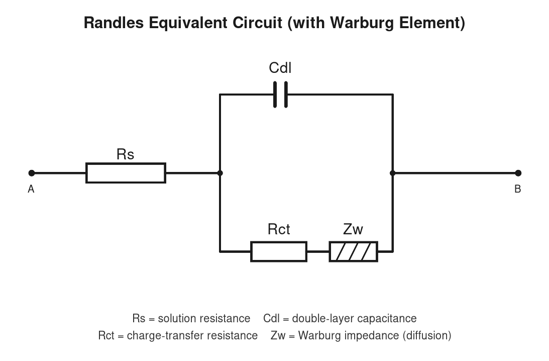
Source: Battery University

Equivalent-circuit values depend on chemistry, construction, temperature, state of charge, aging, frequency, excitation amplitude, and measurement method. They should therefore be understood as condition-dependent parameters, not immutable properties printed on the battery.
Measuring Apparent Resistance with a DC Load
A DC load test estimates apparent resistance from the voltage response to a known current. The basic procedure is:
- Measure the open-circuit voltage after applying the required rest condition.
- Apply a known load for a defined period.
- Measure the loaded voltage and load current.
- Calculate the voltage change divided by the current change.
A simplified expression is:
R apparent = (V open-circuit − V loaded) / I load
The result is called apparent resistance because the pulse includes several processes at once. It does not separately identify ohmic resistance, charge-transfer resistance, capacitance, or diffusion. The value also depends strongly on load magnitude and duration. The test should be selected for the battery size, chemistry, application, and available equipment rather than copied as a universal procedure.
DC loading is used for large stationary batteries and for conventional carbon-pile testing of automotive starter batteries. A load that represents the intended application can reveal whether terminal voltage collapses excessively under current demand. However, a carbon-pile test and a laboratory pulse test are not interchangeable; their currents, durations, connections, and interpretation may differ.
The resolution and repeatability of an instrument are not the same as diagnostic accuracy. A tester may resolve a small voltage change, yet the result can still be dominated by probe resistance, dirty terminals, cable movement, current uncertainty, temperature, or an unsuitable test duration. Four-terminal sensing and clean, secure connections can reduce connection-related error, but they do not remove electrochemical variability.
The measured result is affected by:
- State of charge and recent charging or discharging.
- Battery and ambient temperature.
- Contact and cable resistance.
- Charge acceptance and polarization effects.
- The duration and magnitude of the load pulse.
- The battery’s previous operating history.
A two-tier pulse test can provide additional voltage-response information. It uses a lower-current, longer pulse followed by a higher-current, shorter pulse, or the reverse according to the applicable procedure. Comparing the responses can help separate fast and slower components of the battery’s behavior. It remains a resistance or voltage-response test, however; it does not automatically determine capacity or state of charge.
Safety is essential. High-current tests can produce sparks, hot conductors, arc hazards, and rapid battery heating. Use equipment rated for the battery voltage and current, follow the battery manufacturer’s instructions, prevent short circuits, and provide suitable ventilation where the chemistry can release hazardous gases. A chemistry-specific standard or test procedure should be used only after confirming its current edition, scope, and limits.
AC Conductance and Frequency-Dependent Impedance
An AC conductance or impedance tester applies a small alternating signal and measures the resulting voltage and current response. Unlike a heavy DC load test, this approach usually does not require a large discharge from the battery. It is consequently useful for rapid screening and for applications where repeated high-current loading is undesirable.
The result depends on signal frequency, chemistry, construction, temperature, state of charge, terminal condition, and the instrument’s measurement algorithm. A single-frequency instrument generally reports a combined or apparent response. It does not independently resolve every element in an equivalent circuit.
Commercial conductance testers are widely used for automotive starter-battery assessment and may provide an estimated cranking capability. Such an estimate should not automatically be treated as a standardized capacity or cold-cranking-current test. The instrument’s algorithm, battery database, calibration, and connection quality affect the result.
A 1 kHz impedance measurement can differ substantially from a DC pulse or load-test value because the signal interacts with different electrochemical time constants. Neither result is necessarily wrong. They characterize different portions of the battery’s frequency-dependent response. A DC pulse may be more representative of a defined high-current load, while an AC result can reveal behavior associated with the selected frequency and phase response.
The term “conductance” also requires care. Some instruments calculate a conductance-like value from an AC response; others report impedance magnitude, real resistance, admittance, phase angle, or a proprietary health estimate. These quantities should not be substituted for one another without knowing the instrument’s definitions.
For useful trending, record:
- Test frequency and instrument model or method.
- Temperature and state of charge.
- Rest time and recent charge or discharge activity.
- Terminal and probe conditions.
- The reported value and any associated health or cranking estimate.
AC and DC readings should not be converted with a universal factor. The relationship changes with chemistry, cell design, frequency, temperature, state of charge, and the definition of the reported value. Use the method that best represents the diagnostic question, and compare results only with measurements made using the same method under comparable conditions.
Electrochemical Impedance Spectroscopy for Advanced Diagnostics
Electrochemical impedance spectroscopy (EIS) measures a battery’s response over a range of frequencies. The resulting impedance data can be displayed in formats such as Nyquist or Bode plots and interpreted or fitted with an electrochemical equivalent circuit.
When the data quality and model are appropriate, EIS can help distinguish several contributions, including:
- Ohmic or series resistance.
- Charge-transfer behavior.
- Double-layer or other capacitive effects.
- Diffusion-related processes.
This is a major difference from single-frequency AC testing, which produces a more limited combined response. EIS can provide more diagnostic information than one aggregate resistance value, but it does not make the interpretation automatic. Parameters sometimes labeled as series resistance, charge-transfer resistance, or capacitance are inferred through a model. Their identifiability depends on the selected circuit, frequency range, signal amplitude, data quality, and whether the battery behavior actually matches the model.
Practical EIS work can require specialized equipment, longer test times, stable environmental conditions, careful control of state of charge, and substantial data processing. Temperature, rest period, DC bias, excitation amplitude, frequency range, and cell balancing can all influence the spectrum. Results from a laboratory cell cannot automatically be transferred to a field battery, module, or pack.
EIS also does not directly provide capacity, state of charge, state of health, or cranking capability without validated relationships. Predictions require chemistry-specific calibration and controlled test conditions. Physics-based or statistical models may correlate impedance features with degradation, but the model must be validated for the intended cell design, operating window, and use case.
For these reasons, EIS is best suited to research, development, production characterization, failure analysis, and advanced diagnostics. Routine maintenance generally benefits more from a repeatable, application-appropriate DC or AC method, interpreted together with capacity, temperature, state of charge, and observed application performance.
References
- Battery University | BU-902: How to Measure Internal Resistance. (n.d.). http://www.batteryuniversity.com/article/bu-902-how-to-measure-internal-resistance
- Battery University | How does Internal Resistance affect Performance?. (n.d.). http://www.batteryuniversity.com/article/how-does-internal-resistance-affect-performance
- Internal Resistance of a Battery | Ossila. (n.d.). https://www.ossila.com/pages/internal-resistance-of-a-battery
- How Battery Internal Resistance Impacts Forklift Performance. (n.d.). https://www.fluxpower.com/blog/how-internal-resistance-affects-lift-truck-battery-performance
- Internal Resistance series. Part I: What is internal resistance in a battery? - BioLogic Learning Center. (n.d.). https://www.biologic.net/topics/internal-resistance-series-part-i-what-is-internal-resistance-in-a-battery
- LEAD ACID BATTERY AND ITS INTERNAL RESISTANCE. (n.d.). https://actec.dk/media/documents/68F4B35DD5C5.pdf
- How to Measure Internal Resistance of Lithium Batteries. (n.d.). https://www.large-battery.com/blog/measure-internal-resistance-of-lithium-batteries-methods-guide
- What Internal Resistance Tells Us About Battery Health and How to Measure it - XTAR. (n.d.). https://www.xtar.cc/news/what-internal-resistance-tells-us-about-battery-health-and-how-to-measure-it-261.html
- How Internal Resistance Impacts Lithium Battery Efficiency | Battery Energy Storage System. (n.d.). https://www.battery-energy-storage-system.com/news/internal-resistance-impacts-li-battery.html
- Battery Internal Resistance. (n.d.). https://www.youtube.com/watch?v=c3QLIaXHVK0&xstg=CAMSBhUDzO3xHw%3D%3D