Internal resistance is one of the main reasons a battery that appears charged can still perform poorly. A cell or pack may have acceptable open-circuit voltage and remaining capacity, yet fail when a device demands current. The missing factor is the resistance inside the cell and throughout the current path of the pack.
In battery work, internal resistance is usually expressed in milliohms (mΩ). A low-resistance battery can deliver current with less voltage drop and less heat generation. A high-resistance battery behaves more like a restricted supply: voltage falls sharply under load, useful power is reduced, and the battery or protection system may shut the device down early.
This matters most in high-drain applications. A phone radio burst, a power tool motor, an inverter, or an electric powertrain can draw current fast enough that resistance becomes the limiting factor rather than nameplate capacity alone.
Why Internal Resistance Limits Battery Performance
Internal resistance is the opposition to current flow inside a battery cell or pack. It comes from electrochemical processes inside the cell and from physical conductors in the current path. At the cell level, it includes ionic movement through electrolyte and porous electrodes, electronic conduction through current collectors and active materials, and interface effects that change with condition and state of charge. At the pack level, it also includes connections, protection devices, wiring, and electronics.
A useful simplified model treats the battery as an ideal voltage source in series with a small resistance. Under load, the terminal voltage is lower than the open-circuit voltage:
terminal voltage ≈ open-circuit voltage − current × internal resistance
The same resistance also turns some energy into heat:
heat loss ≈ current² × resistance
These relationships explain why high-current applications are so sensitive to resistance. Doubling the current doubles the voltage drop for the same resistance, and the heat loss rises with the square of current. A resistance value that is tolerable in a low-power device can become a serious performance limit in a motor drive, power tool, or traction battery.
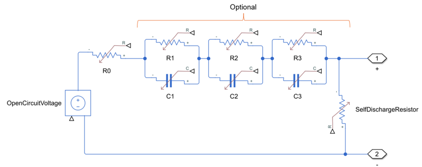
Source: Battery University

Capacity alone therefore does not guarantee usable performance. A battery can still store energy but be unable to deliver that energy at the required rate. This is why an aged pack may run a light load but collapse when powering a motor, heater, transmitter, or compressor.
Common effects of rising internal resistance include:
- Voltage sag under load. The device sees a lower voltage whenever current demand rises.
- Reduced power delivery. Less voltage at the terminals means less usable electrical power.
- Lower efficiency. More stored energy is lost as heat instead of reaching the load.
- Heating during charge or discharge. Higher resistance increases internal heat generation.
- Early cutoff. Protection circuits may interpret voltage sag as a low-battery condition.
- Reduced high-load runtime. Runtime may appear acceptable at light load but fall sharply under heavy load.
Internal resistance is not a fixed value. It varies with chemistry, cell size, construction, state of charge, temperature, age, and measurement method. Low temperature commonly increases resistance because electrochemical processes slow down. Aging also tends to increase resistance as internal materials change and interfaces degrade. Pack layout matters as well: two batteries using similar cells can behave differently if their interconnects, protection circuits, or contacts are different.
Pack Resistance: More Than the Cells
The internal resistance measured at a battery pack’s external terminals is not only the resistance of the cells. It is the total resistance of the complete current path. This distinction is important because many service tests and rapid battery testers measure the pack as a system, not the bare cell.
Typical pack-level contributors include:
- cell internal resistance
- welded tabs or nickel strips
- busbars and interconnects
- spot welds, ultrasonic welds, or soldered joints
- fuses and current interrupt devices
- positive temperature coefficient (PTC) protection devices where used
- MOSFETs or switching devices in protection electronics
- current-sense elements
- printed circuit board traces
- pack wiring
- connectors, terminals, and spring contacts
- contamination, wear, or looseness at external contacts
The reference example emphasizes that these peripheral components can more than double the measured resistance in some packs. That is a critical point: if a tester reports high resistance, the cause may not be the electrochemical cell alone. A weak weld, aged contact, undersized conductor, or protection-board path can produce a high pack reading even if the cells themselves are not the only problem.
This also affects interpretation of rapid tests. A cell-only assumption can be misleading when the measurement is taken at pack terminals. For example, a small single-cell pack may include a protection circuit board and thermal protection device that add a large share of the total resistance. A high-current tool pack may have very low-resistance cells, but its usable performance still depends on weld quality, busbar design, BMS switching devices, and connector condition.
Modern battery packs add further complexity. A battery management system may include MOSFETs, current measurement components, temperature sensors, balancing circuits, and communication electronics. Not all of these components are in the main high-current path, but the parts that are in series with the load can affect voltage drop and heating. In high-current packs, connector design and contact pressure are also important because even a small added resistance can become significant at high current.
For diagnosis, it is useful to separate three ideas:
- Cell resistance — the electrochemical and internal conductor resistance of the individual cells.
- Connection resistance — welds, tabs, busbars, wires, and terminals.
- Protection-path resistance — fuses, PTC devices, MOSFETs, current shunts, and PCB copper in the load path.
A complete pack measurement includes all three. That is often what matters to the device, but it must be interpreted correctly.
Mobile Phone Battery Resistance Example
A single-cell mobile phone battery is physically small, but its measured resistance at the pack terminals can include several non-cell contributors. The historical example in the source breaks down a phone battery pack into a prismatic cell, welded connection, PTC device, cable connection, and protection circuit board.
The example values are:
| Contributor in the single-cell phone pack | Example resistance |
|---|---|
| High-capacity prismatic cell | 50 mΩ |
| Welded connection | 1 mΩ |
| PTC welded to cable and cell | 25 mΩ |
| Protection circuit PCB | 50 mΩ |
| Approximate total internal resistance | 130 mΩ |
The PTC value in the example is noted as being in the 18–30 mΩ range according to the cited specification, with 25 mΩ used in the breakdown. The total is approximately 130 mΩ, not because the cell alone is 130 mΩ, but because the cell is only one part of the measured pack path.
This example illustrates two practical lessons.
First, in a compact consumer battery, the protection circuit and safety elements can be a major part of the measured resistance. These parts are present for important safety and control reasons, but they still affect load performance.
Second, the total resistance is design-specific. Modern phone batteries may differ substantially from this example because manufacturers use different cell formats, tab arrangements, protection layouts, charging architectures, and connector systems. Fast-charging designs also place strong demands on thermal management and current-path resistance. A current phone pack should therefore not be assumed to have exactly the same resistance as the historical example.
The performance symptom, however, remains relevant. A phone battery can show a reasonable state-of-charge estimate under light load and then shut down when the processor, display, modem, camera, or wireless subsystem draws a current pulse. The open-circuit voltage may recover after the shutdown or after the load is removed, making the battery appear less empty than the device behavior suggested. That pattern is consistent with voltage sag caused by internal resistance.
Temperature can make the effect more visible. In cold conditions, resistance rises and voltage sag increases. A phone that works normally at room temperature may shut down early outdoors because the same load produces a larger voltage drop. Aging can have a similar effect because resistance tends to increase as the battery wears.
Power Tool Battery Pack Resistance Example
A power tool battery pack is a more demanding example because motor loads can draw high current. Drills, saws, grinders, impact drivers, and similar tools often require brief but intense current bursts, especially at startup, under stall conditions, or when cutting dense material. Under those conditions, internal resistance directly affects torque, speed stability, heat generation, and cutoff behavior.
A typical power tool pack contains multiple cells connected in series and often in parallel. The complete resistance includes the cells plus the hardware needed to combine them and deliver current to the tool. Important contributors can include:
- cylindrical lithium-ion cells or another cell format selected for high-drain service
- nickel strips, copper busbars, or laminated interconnects
- individual weld points between cells and interconnects
- series links between cell groups
- current-sense components
- thermal fuses or protective devices where used
- BMS switching components where the pack design places them in the current path
- internal pack wiring or bus structures
- external blade, rail, or slide contacts
- tool-side contact resistance
Power tools are more affected by resistance than low-drain devices because current is high. A small resistance rise produces a larger voltage drop when current demand increases. If terminal voltage falls below the tool or pack cutoff threshold, the tool may stop even though the cells still contain energy. The user experiences this as loss of torque, pulsing, sudden cutoff, or a pack that seems to be empty during heavy work but recovers partly after resting.
Heating is also more important in tool packs. Since heat loss rises with current squared, resistance in a weld, busbar, contact, or cell group can produce localized heating. Uneven resistance is especially undesirable because one connection or cell group may run hotter than the rest of the pack. Modern packs commonly monitor temperature and may limit output or stop operation to protect the cells.
Pack design has a major influence on resistance. Two packs with the same nominal voltage and amp-hour rating can perform differently if they use different cell models, different parallel group sizes, different interconnect materials, or different connector systems. A pack built for compact size may not behave like a pack built for maximum discharge current. Likewise, a high-capacity pack is not automatically a high-power pack unless its cells and current path are designed for high current.
The original power-tool example is useful because it points attention beyond the cells. In a multi-cell pack, every weld, strip, busbar, and terminal is repeated many times. Small resistances add up, and poor connections can dominate the pack’s behavior. For this reason, pack-level resistance measurement is best interpreted along with inspection of contacts, operating symptoms, temperature behavior, and comparison to a known-good pack of the same design.
Modern tool packs vary widely by manufacturer and platform. Cell type, series/parallel arrangement, BMS design, current rating, cooling design, and connector geometry all affect resistance. Universal resistance limits should therefore be avoided. The meaningful comparison is usually between packs of the same model, measured at similar temperature, state of charge, and test conditions.
Practical Signs of Rising Internal Resistance
Rising internal resistance often appears first as a load-related problem rather than a simple loss of open-circuit voltage. A battery may measure normally with a voltmeter and still fail in actual use because the voltage collapses only when current demand rises.
Common symptoms include:
- sudden device shutdown during high load
- tool motor bogging, pulsing, or cutting out
- reduced acceleration or peak power in traction applications
- shorter runtime during heavy load while light-load runtime seems less affected
- battery voltage recovering after the load is removed
- pack or device becoming warmer than expected during normal use
- charger reducing current or taking longer because the pack heats or reaches limits
- inconsistent performance in cold weather
- one pack performing noticeably worse than another pack of the same model and age
The most important diagnostic idea is that voltage must be evaluated under load. Open-circuit voltage is useful, but it does not show the voltage drop caused by internal resistance. A weak high-resistance battery can look acceptable with no load and then fall below the equipment’s operating threshold when current is demanded.
Internal resistance readings are also most useful when compared with a baseline. A new or known-good battery of the same model, measured with the same instrument and method, provides a better reference than a universal pass/fail number. Acceptable resistance depends on chemistry, cell size, pack voltage, parallel count, temperature, state of charge, and required current.
Measurement method matters. A DC load test estimates resistance from the voltage change at a known current. AC impedance methods use a small test signal and can produce a different value because they include frequency-dependent electrochemical behavior. Both approaches can be useful, but their results should not be mixed casually.
For practical service work, control the test conditions as much as possible:
- Compare batteries of the same design.
- Measure at similar state of charge.
- Allow packs to reach similar temperature.
- Use the same tester and method.
- Record trends over time rather than relying on one reading.
- Inspect contacts and connectors before blaming the cells.
A rising resistance trend is often more meaningful than a single measurement. If a pack’s resistance steadily increases, and the user also reports voltage sag, heating, or early cutoff, the evidence points toward reduced power capability. The pack may still store energy, but it is no longer able to deliver that energy efficiently at the required current.
Safety should also be considered. A battery that becomes unusually hot during ordinary charge or discharge, shows swelling, has damaged terminals, or repeatedly trips protection should be removed from service and evaluated according to the equipment manufacturer’s instructions. Internal resistance is primarily a performance parameter, but excessive resistance can contribute to heat generation and stress in the pack.
The practical conclusion is simple: capacity describes how much charge a battery can store, while internal resistance strongly influences how well it can deliver that charge. For real equipment performance, especially in high-drain devices, both must be considered together.
References
- Battery University | BU-802a: How does Rising Internal Resistance…. (n.d.). http://www.batteryuniversity.com/article/bu-802a-how-does-rising-internal-resistance-affect-performance
- Effects of Internal Resistance in Circuits | PDF | Electrical .... (n.d.). https://www.scribd.com/document/696053476/Investigating-Internal-Resistance-in-Electrical-Circuits
- A Guide to Understanding Battery Internal Resistance - XTAR. (n.d.). https://www.xtar.cc/news/a-guide-to-understanding-battery-internal-resistance-258.html
- How internal resistance affects battery performance. (n.d.). https://news.pcim.mesago.com/how-internal-resistance-affects-battery-performance-a-3b8f8a5d2abe9abec61f973ea4c3a7f9
- Guide to Battery Internal Resistance & Health | Fanttik. (n.d.). https://fanttik.com/blogs/support/battery-internal-resistance-health-guide
- How Battery Internal Resistance Impacts Forklift Performance. (n.d.). https://www.fluxpower.com/blog/how-internal-resistance-affects-lift-truck-battery-performance
- How Internal Resistance Impacts Lithium Battery Efficiency. (n.d.). https://www.battery-energy-storage-system.com/news/internal-resistance-impacts-li-battery.html
- Battery Internal Resistance: Power Losses, Heat, and Degradation | Ionworks | Ionworks. (n.d.). https://ionworks.com/blog/internal-resistance
- Battery Internal Resistance. (n.d.). https://www.youtube.com/watch?v=c3QLIaXHVK0
- Internal Resistance series. Part I - Bio-Logic. (n.d.). https://www.biologic.net/topics/internal-resistance-series-part-i-what-is-internal-resistance-in-a-battery