Battery packs are built from cells arranged to meet the voltage, capacity, current, size, and safety requirements of a device. A single cell may be enough for a clock, phone, or memory-backup circuit, but many applications need more voltage than one cell can provide or more runtime than one cell can store.
The two basic electrical building blocks are series and parallel connections. Series connections add cell voltage. Parallel connections add available capacity and current capability while keeping the same nominal voltage. Many practical packs, including laptop batteries, e-bike batteries, power-tool packs, electric-vehicle modules, and energy-storage systems, combine both methods.
Correct configuration is not only an electrical design choice. Cell matching, insulation, protection devices, battery-management electronics, charging method, and service procedure all affect reliability and safety. The same simple series and parallel rules apply across battery chemistries, but the acceptable voltage limits, charge method, protection requirements, and failure behavior depend on the specific cell type.
Source: Battery University
Single-Cell Battery Applications
A single-cell battery pack is the simplest configuration. There is no series string to balance, and there are no parallel cells that must share current. In small rechargeable products, the protection circuit can often be simpler than it would be in a multi-cell pack, although it still must match the chemistry and product requirements.
Common single-cell applications include:
- Mobile phones and many tablets using one lithium-ion cell
- Wall clocks using one alkaline cell
- Wristwatches using small primary cells such as silver-oxide types
- Memory-backup circuits and other very low-power loads
- Small sensors, remotes, and portable electronics where one cell provides adequate voltage
Nominal voltage is chemistry-dependent. It is an approximate working voltage used for design and labeling, not a fixed value at every state of charge. Exact values vary by cell chemistry, manufacturer, load, temperature, and state of charge.
| Cell chemistry | Typical nominal cell voltage |
|---|---|
| Nickel-based rechargeable cells | 1.2 V |
| Alkaline primary cells | 1.5 V |
| Silver-oxide primary cells | 1.6 V |
| Lead-acid cells | 2.0 V |
| Primary lithium cells | about 3.0-3.9 V |
| Lithium-ion cells | about 3.6 V |
| Lithium iron phosphate, LiFePO4 | about 3.2 V |
| Lithium-titanate cells | about 2.4 V |
These nominal values explain why a single-cell design is practical in some products but not in others. A wall clock can operate from a 1.5 V alkaline cell because its power demand is low and the electronics are designed for that voltage range. A laptop, power tool, or e-bike needs a higher system voltage and therefore uses multiple cells.
Series Connections for Higher Voltage
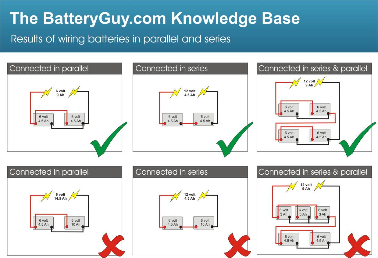
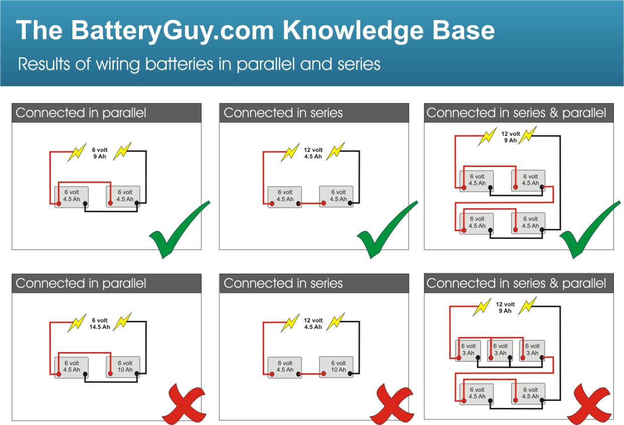
A series connection links the positive terminal of one cell to the negative terminal of the next. The pack output is taken from the two remaining end terminals. In this arrangement, the voltages add, while the amp-hour capacity remains roughly the same as that of one cell or one parallel group in the string.
For example, four lithium-ion cells with a nominal voltage of about 3.6 V each produce a nominal string voltage of about 14.4 V when connected in series. A common 12 V lead-acid battery is built from six lead-acid cells of about 2.0 V nominal voltage each. The same principle applies whether the cells are cylindrical lithium-ion cells, prismatic cells, pouch cells, or lead-acid plates assembled inside one case.
Series connection is used when the load or power electronics need higher voltage. Higher voltage can reduce current for the same power level, which can help reduce conductor size and resistive losses, but it also raises insulation, clearance, monitoring, and service requirements.
Series strings require closely matched cells or cell groups. The same current flows through every series element, so the weakest cell tends to limit the usable pack capacity. If one cell has lower capacity, higher internal resistance, or greater self-discharge, it may reach its discharge limit before the rest of the string. During charging, a mismatched cell may reach its upper voltage limit earlier than the others.
For rechargeable packs, monitoring and balancing become increasingly important as the number of series cells increases. A battery management system or protection circuit may monitor cell-group voltages, pack current, and temperature, and may stop charge or discharge when limits are reached. High-voltage packs should be designed, tested, and serviced only with appropriate procedures and qualified personnel, because shock, arc, and stored-energy hazards can be substantial.
Why Tapping a Series String Causes Imbalance
A tempting shortcut is to tap partway along a series string to obtain a lower voltage for an auxiliary load. For example, a designer might use only part of a larger battery string to supply a fan, lighting circuit, controller, or accessory rail.
The problem is that the tapped section then carries a different load from the rest of the string. Those cells or modules discharge faster than the untapped cells. During recharge, the pack charger usually sees the total string, not the uneven history of each section. The result can be imbalance between cells or modules.
Imbalance reduces usable capacity because the pack must stop discharging when the weakest or most depleted cell group reaches its lower limit. It can also shorten life by repeatedly overworking part of the battery. In severe cases, a tapped section can be pushed toward overdischarge during use or overcharge during recovery charging, depending on the design and chemistry.
A better engineering approach is usually to power auxiliary loads through a properly rated DC-DC converter or a separately designed auxiliary supply. That keeps the main series string loaded evenly and allows the auxiliary circuit to be fused, isolated, and regulated according to its own requirements.
Parallel Connections for Higher Capacity and Runtime
A parallel connection ties like terminals together: positive to positive and negative to negative. The nominal voltage remains the same as one cell, but the available capacity increases. If two matched cells are connected in parallel, the parallel group has approximately twice the amp-hour capacity of one cell. It can also provide higher current capability when the cells, interconnects, and protection system are designed for that current.
Parallel groups are useful when a product needs longer runtime at the same voltage. They are also used as building blocks in larger packs: first, cells are placed in parallel to create a higher-capacity group; then several groups are connected in series to reach the required pack voltage.
Cells placed in parallel should have the same chemistry, nominal voltage, capacity class, age, condition, and state of charge before connection. Connecting cells at different voltages can cause high equalization currents. Mixing chemistries or cell types can also create unequal charge and discharge behavior that the protection system may not be able to manage correctly.
A failing cell in a parallel group can affect the rest of the group. If a cell becomes internally shorted or develops abnormal leakage, the other cells in parallel can feed current into the fault. Pack designers may use protective practices such as:
- Cell-level fusing or fusible links in large parallel arrays
- Current-interrupt devices built into some cylindrical cells
- Positive temperature coefficient devices where applicable
- Pack-level fuses or electronic overcurrent protection
- Temperature sensing and monitoring by a protection circuit or BMS
The correct protection method depends on chemistry, cell format, pack size, expected fault current, and certification requirements. Parallel connection is not inherently unsafe, but it must be treated as a high-energy current-sharing design problem rather than a simple wiring convenience.
Series-Parallel Packs for Voltage and Capacity
Series-parallel packs combine both methods. Parallel cells increase the capacity of each group, and series-connected groups raise the overall voltage. This is one of the most common arrangements in lithium-ion products because a single cell rarely provides both the voltage and runtime required by the system.
A typical laptop-battery example is a 4s2p lithium-ion pack. Four cell groups are connected in series to provide a nominal voltage of about 14.4 V when using 3.6 V lithium-ion cells. Each series group contains two cells in parallel, so the capacity is approximately doubled compared with a single-cell group. If each cell is 2,400 mAh, the parallel pair is about 4,800 mAh, while the series count determines the nominal voltage.
Series-parallel construction appears in many battery-powered systems, including:
- Laptop computer packs
- Cordless power-tool batteries
- E-bike and scooter packs
- Electric-vehicle battery modules
- Portable power stations
- Larger stationary energy-storage systems
Mechanical design is as important as the electrical schematic. Cells must be held securely, insulated from one another where needed, and protected from abrasion or puncture. Conductive metal cell cans, nickel strips, busbars, and module hardware can create short-circuit paths if insulation is inadequate. Insulating rings, fishpaper, plastic cell holders, separators, and properly routed interconnects are common design elements used to reduce short-circuit risk.
Configuration Notation: Understanding 2s2p, 4s2p, and Similar Labels
Battery-pack notation often uses the form XsYp, where s means series and p means parallel. The number before s identifies how many cells or parallel cell groups are connected in series. The number before p identifies how many cells are connected in parallel in each group.
Examples:
- 2s1p: two cells in series, one cell per group. Voltage is doubled; capacity is about the same as one cell.
- 2s2p: two series groups, with two cells in parallel in each group. Voltage is doubled; capacity is about doubled.
- 4s2p: four series groups, with two cells in parallel in each group. For 3.6 V lithium-ion cells, nominal pack voltage is about 14.4 V, and capacity is about twice that of one cell.
The notation is especially common in lithium-ion pack design, hobby packs, e-bike batteries, and portable electronics. The underlying principles are not limited to lithium-ion cells. Nickel-based, lead-acid, alkaline, and primary lithium cells can also be arranged in series or parallel when the chemistry, cell design, and protection approach permit it. In all cases, the pack designer must use the correct voltage limits and safety practices for the chemistry involved.
Protection Devices Used in Series and Parallel Battery Packs
Battery protection is layered. No single device is suitable for every chemistry, pack size, or fault condition. A small single-cell lithium-ion pack may rely on a compact protection circuit and cell-level safety features. A large rechargeable pack may require a full battery management system, contactors, fuses, thermal sensors, isolation monitoring, and controlled service procedures.
Common protection elements include:
- PTC devices: resettable devices whose resistance increases when temperature or current becomes excessive, reducing current flow in some fault conditions.
- Current interrupt devices, or CIDs: cell-integrated mechanisms used in some cells to interrupt current under defined internal pressure or fault conditions.
- Thermal cutoffs: devices that open a circuit when a specified temperature is exceeded.
- Fuses: sacrificial overcurrent devices used at pack, module, string, or sometimes cell level.
- Protection circuits: electronic circuits that disconnect or limit operation during overvoltage, undervoltage, overcurrent, short-circuit, or temperature faults.
- Battery management systems: systems that monitor cell-group voltage, current, and temperature, and may provide balancing, state estimation, fault logging, and charge/discharge control.
Some protections are built into individual cells. Others are part of the pack wiring, charger interface, or system controller. Large packs often rely more heavily on pack-level engineering because the energy and fault currents can exceed what small cell-level components can safely handle alone.
Protection design must consider both series and parallel behavior. In series strings, the main concern is that individual cells can drift apart in voltage and state of charge. In parallel groups, the concern includes high current flow into a faulted cell or interconnect. A robust pack design accounts for both.
Safe Use Guidelines for Household Primary Batteries
Primary batteries are non-rechargeable cells. Common household examples include alkaline, zinc-air, silver-oxide, and some lithium primary cells. They are convenient and reliable when used correctly, but misuse can cause leakage, overheating, rupture, or equipment damage.
Practical guidelines include:
- Insert cells with the correct polarity. Match the positive and negative markings on the device.
- Do not force a cell into a compartment. Forced insertion can damage wraps, terminals, springs, or insulation.
- Keep battery contacts clean and dry. Dirty or corroded contacts increase resistance and may cause intermittent operation.
- Replace all cells in a multi-cell device at the same time when practical.
- Do not mix old and new cells in the same device.
- Do not mix different chemistries, brands, capacities, or states of charge.
- Remove cells from devices that will be stored for long periods, especially if leakage could damage the equipment.
- Store loose cells so their terminals cannot short against coins, keys, tools, or other batteries.
Primary batteries should not be recharged unless they are explicitly designed and labeled for that purpose. Attempting to recharge ordinary primary cells can cause gas generation, leakage, rupture, or fire.
Disposal and recycling rules vary by location and chemistry. Many communities provide battery recycling programs, and lithium primary cells in particular should be handled according to local waste and transport requirements. When in doubt, follow the cell manufacturer’s instructions and local regulations.
Safe Use Guidelines for Rechargeable Batteries
Rechargeable batteries require correct charging as well as correct use. The charger must match the chemistry, voltage, cell count, and pack configuration. A charger intended for one chemistry may use voltage limits or charge termination methods that are unsafe for another.
Observe polarity whenever installing rechargeable cells. Reverse installation can damage equipment and may force a cell into reverse charge in a multi-cell string. Reverse charging is especially harmful because it can cause internal damage, heating, leakage, or pressure buildup depending on the chemistry.
Avoid these practices:
- Charging with an incompatible charger
- Overcharging or bypassing the protection circuit
- Charging cells with torn wraps, dents, corrosion, leakage, or swelling
- Charging outside the manufacturer’s recommended temperature range
- Charging packs with unknown cell condition or unknown configuration
- Mixing rechargeable cells of different chemistry, capacity, age, or state of charge in the same pack
Rechargeable cells should generally be charged at room temperature unless the manufacturer specifies another allowable range. Low-temperature and high-temperature charging both require chemistry-specific limits. Lithium-ion cells, for example, are particularly dependent on controlled voltage, current, and temperature during charging.
Inspect cells and packs periodically. Damaged insulation on cylindrical cells can expose conductive metal cans and create short-circuit risk when the cell is placed in a holder or pack. Swollen pouch cells, leaking cells, hot cells, or cells with unusual odor or discoloration should be removed from service according to safe handling procedures.
For engineered packs, follow the manufacturer’s instructions rather than modifying the wiring, replacing individual cells casually, or bypassing the BMS. Series and parallel connections are simple electrical concepts, but real battery packs store enough energy to require disciplined design, protection, and maintenance.
References
- Battery University | BU-302: Series and Parallel Battery…. (n.d.). http://www.batteryuniversity.com/article/bu-302-series-and-parallel-battery-configurations
- series-and-parallel-configuration-of-lithium-battery. (n.d.). https://www.mathaelectronics.com/series-and-parallel-configuration-of-lithium-battery
- Battery configurations (series and parallel) and their protections - Battery Power Tips. (n.d.). https://www.batterypowertips.com/battery-configurations-series-and-parallel-and-their-protections
- Safety Tips for Connecting Batteries in Series and Parallel — Large Battery. (n.d.). https://www.large-battery.com/blog/safety-battery-series-parallel
- Lithium Battery Safety Procedure. (n.d.). https://www.whoi.edu/fileserver.do?id=232144&pt=2&p=19610
- Battery Pack Configuration Explained | PDF | Rechargeable Battery | Series And Parallel Circuits. (n.d.). https://www.scribd.com/document/418024217/Battery-Configurations
- How To Connect Batteries In Series and Parallel | BatteryStuff.com. (n.d.). https://www.batterystuff.com/kb/articles/battery-articles/battery-bank-tutorial.html
- The Lithium Battery Architecture Handbook: A Systems .... (n.d.). https://eneronix.com/the-lithium-battery-architecture-handbook-a-systems-guide-to-cells-bms-and-internal-engineering
- Understanding battery configurations for electronics projects. (n.d.). https://www.facebook.com/groups/246591440943423/posts/1004797185122841
- Connecting lithium batteries in series: safety and best .... (n.d.). https://www.facebook.com/groups/327149613069631/posts/1003051358812783